

Designing Test Fixtures in SMT Assembly
The most popular way to produce electronic pcb smt assembly is through surface mount technology (SMT). From the flip phone in your pocket to the tablet in your hands, these and other devices utilize SMT. SMT has a number of advantages over through hole technology, such as:
It allows much higher component density and more connections per board area. It also enables components to be placed on both sides of the board, allowing engineers to maximize use of space in small electronic products. Another advantage of SMT is its cost savings. Because it uses much less solder than THT, production costs are lower. This makes SMT an attractive option for high-volume production runs, where economies of scale can lower the cost per unit.
SMT is based on the use of solder joints to make mechanical and electrical connections between component and circuit board. As a result, any flaws in these joints can undermine the reliability of the assembly. Therefore, testing and debugging are important parts of the PCB manufacturing process. To ensure that the assembly is working as it should, a test fixture is necessary to perform both in-circuit and functional tests. The design of a test fixture is a complex task, and depends on many variables including the number, size, and spacing of the test points on the board. It is also influenced by the product’s functionality and manufacturing volumes.
In order to perform a test, a fixture must have a means to physically contact each of the test points on the PCB. This is typically accomplished through the use of test probes that are attached to interface hardware. These allow the circuit board to communicate with external test equipment such as oscilloscopes, multimeters, or automated test systems.
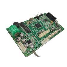
Key Considerations for Designing Test Fixtures in SMT Assembly
There are a variety of different types of test probes available, including pogo pins, spring-loaded contacts, or needle probes. In addition to making physical contact with the test points on a circuit board, test probes can transmit electronic signals to the testing equipment. In general, the test probes must be able to withstand both heat and force. Depending on the type of test needed, a fixture may also need to be capable of providing a high-resolution image of the circuit board’s surface.
Whether a simple test fixture is required or a more complex one, the key to success lies in the initial planning of the design. Sound Design for Manufacture and Assembly (DFMA) practices can improve quality, lower manufacturing costs, and shorten delivery lead times. Often, errors in production are caused by mistakes that could have been avoided through good DFMA.
In order to avoid these errors, it is imperative to consult with a CM early in the project. They will be able to offer tips and guidance to help design a successful test fixture that will meet your specific needs.
Investing in high-quality stencils can lead to significant cost savings in the long run. Although the initial cost of a high-quality stencil might be higher, the reduction in defects, rework, and production downtime translates into lower overall production costs. Additionally, stencils can be reused for multiple production runs, providing ongoing value.


