

Flex Circuit Boards Can Be Used in Automotive Electronics
In the automotive industry, flex circuit boards can be used to help improve connectivity and efficiency in various systems. Flex PCBs offer several benefits, including lower weight and cost, increased reliability and design flexibility. They are also able to better dissipate heat from high-performance electronic components. Flex PCBs can be used in new energy vehicles to provide efficient connections for sensors, BMS, car displays, and entertainment systems.
Miniaturization is an important trend in the automotive electronics industry, and flex circuit boards can help to keep up with this demand. They are more space-efficient than rigid PCBs, and they can be bent to fit into narrow spaces and other areas that would otherwise be inaccessible to rigid boards. They can also be repositioned during installation to accommodate changes in position. This helps to ensure that your vehicle’s electronic systems are positioned correctly for maximum performance.
Flex PCBs can also be used to reduce the number of mechanical components and connectors that are needed in a circuit board, which can lead to significant savings during assembly. Streamlined assembly processes can also decrease material costs, as well as lower production time and labor. In addition, flex PCBs are known for their ability to efficiently dissipate heat from high-performance electrical components, which can protect them from overheating.
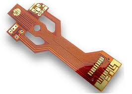
How Flex Circuit Boards Can Be Used in Automotive Electronics
When designing a flex PCB, it is important to consider the materials that will be used in its construction. The different types of coverlay, solder mask, and stiffeners will all influence the final product. The thickness of the flex PCB is also an important factor, as it can affect its bending capabilities. If your flex circuit board will be subject to a lot of bending, it is best to use thinner copper traces. This will decrease the resistance to bending and increase the durability of the board.
Another key consideration is the location of vias and holes. It is recommended to place these features away from the bending regions of the circuit board, as they may be prone to cracking or lifting due to stress. In addition, it is helpful to include a tear stop or tear guard in the area of the circuit that will be subjected to high-flexing. This will prevent the traces from tearing or detaching from the board.
It is also important to use rounded edges on a flex PCB, as sharp edges can increase the risk of damage during bending. Additionally, it is a good idea to avoid using solid polygons as this will make the board less flexible. Instead, hatched polygons are preferred as they are more resilient to flexing.
In order to ensure that your flex PCB will bend without causing any damage, it is important to use proper CAD layouts and engineering practices. For example, it is recommended to use pad-only plating for flex PCBs as this can help to minimize copper waste and improve etch yields. In addition, it is essential to ensure that all vias and pads are adequately sized. Lastly, it is important to use an annular ring on all vias and pads that are thinner than 20 mil in order to improve their strength against shear force and vibrations.